


- Advanced Interconnect Technologies
- 2.5 & 3D Heterogeneous Integration
- System in Package (SiP)
- Wafer Bumping & WLP
- Multi-Chip Modules (MCMs)
- Novel Microfabrication & MEMS
- Design, Packaging & Assembly
- Assembly Services
- Final Test
- Chip on Board (CoB)
- Plastic Packaging (BGA/CSP/QFN)
- Hermetic Packaging
- MIL-STD-1553 Data Bus Couplers & Accessories
- Micro In-Line Couplers
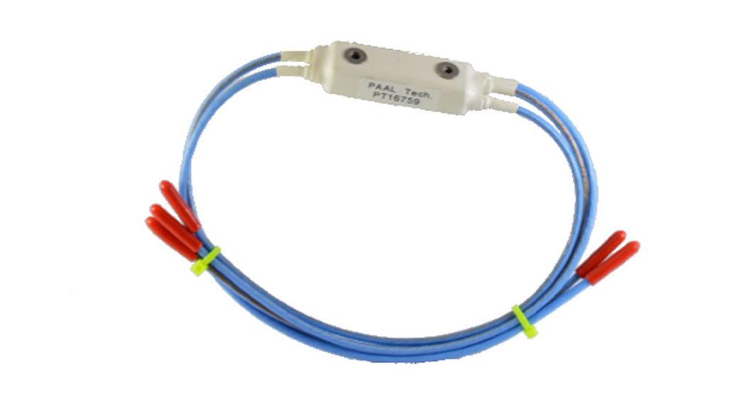
- Tab Mounted In-Line Couplers
- Through Hole Mounted In-Line Couplers
- Box Couplers
- Custom Design Couplers
- Data Bus Coupling Transformers
- Data Bus Relays
- Data Bus Harnesses
- Bus and Stub Terminators
- Wide Bandwidth RF & Video Transformers
- Antenna Couplers
- Video Isolation Transformers
- RF Wideband Transformers
- RF Wideband Transformers & Impedance Adapters
- Mounting holes designed for 6-32 hardware
- Bus and Stub cable markers provided
- Offers full performance features of micro in-line couplers plus the option of mounting
- Single and dual terminated units available
- MIL-STD-1553 A or B designs available
- Flight rated
Electrical Specification (In Accordance with MIL-STD-1553B)
| Transformer Turns Ratio (N) | 1.41:1 (+/-3%) |
|---|---|
| Transformer Droop | < 20% |
| Overshoot & Ringing | < +/- 1v pk-pk |
| Common Mode Rejection | > 55 dB at 1MHz |
| Fault Isolation Resistance (R1, R2, ...) | 59.0 Ohms, 1%, 1 watt (MIL-R-39007) |
| Operating Temperature | -55°C to +125°C |
| Construction | CRS Case, Tin-Lead Plated and Painted for 100% EMI & Environmental Seal |
| Bus Termination Resistor | 78.7 Ohms, 1%, 1 watt (MIL-R-39007) |
Environmental Specifications
| Random Vibration | MIL-STD-202, Method 204, Condition B, 12 Hours Per Axis |
|---|---|
| Mechanical Shock | MIL-STD-202, Method 213, Condition I |
| Pull Strength | 12 lbs. on Each Cable |
| Thermal Shock | MIL-STD-202, Method 107, Condition B, -65°C to +125°C, 10 Cycles |
| Life | MIL-STD-202 Method 108, 1000 Hours at 125°C (14v pk-pk, 1 MHz sq. Wave Input at Stub, 100% Duty Cycle and 78 Ohm Bus Termination) |
| Moisture Resistance | MIL-STD-202, Method 106 |
| Resistance to Solvents | MIL-STD-202, Method 215 |
| Altitude | > 250,000 ft. Operational |
| Thermal Vacuum | 10E-5 mm Hg, Operational and -90°C to +71°C |
| Surface Transfer Impedance | 20 milli Ohms/Meter Max for Single Shield Cable and 10 milli Ohms/Meter Max for Double Shield Cable |
Standard Models
| No. of Stubs | Model No. | Coupler Body Dimensions (Inches) Incl. Environmental Jacket | Wt. Excl. Cable (grams) | RFQ | RFI | Tech Support |
|---|---|---|---|---|---|---|
| 1 | BC0110 | 0.53x0.78x1.28 | 18 | RFQ | RFI | Tech Support |
| 2 | BC0120 | 0.56x0.80x1.50 | 28 | RFQ | RFI | Tech Support |
| 3 | BC0130 | 0.71x0.98x1.87 | 40 | RFQ | RFI | Tech Support |
| 4 | BC0140 | 0.87x1.07x2.25 | 55 | RFQ | RFI | Tech Support |